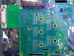
BMS/Architecture
From Unofficial Zero Manual
Some general speculation here about how the BMS is designed and arranged, correlated with BMS board examination.
- TI PL536
- Stackable Cell Monitor With Overvoltage Protector and Balancing
- The product identifier "PL536" occurs in BMS logs, referring to a TI BMS chip that handles 3-6 cells in series.
- The Zero BMS has 5 of these (visible on the front of the board above).
- The 5 chips divide up the 28 cell series into groups that each chip monitors (seemingly 6 per chip until the last chip handles 4 for a total of 28).
- References
- BMS tutorial
- BMS on wikipedia
