This describes installing appropriately crimped and terminated cables onto the Sevcon controller's DC terminals.
 Warning: Warning: | This procedure, if performed imprecisely, can result in irreversible damage to your powertrain, fire, injury, and even death. |
- Motivation
- The officially recommended charging inlet is the Accessory Charging Port, which is fused to less than the 1C limit.
- In order to achieve 1C charging, some bypass is required for at least one charging subsystem.
- One may run one charging system through the port and one through the controller.
- Mechanism
- The Sevcon Gen4 controller has a series of terminals: M1, B-, M2, B+, M3.
- B+ and B- are battery side terminals used mostly for input power but also supply power back to the battery via regen.
- Requirements
- Planned route and matching cable length from the controller to the charger.
- See the Sevcon Gen4 product manual under Connecting power cables.
- Keep cable runs short
- Minimize current loops by keeping positive and negative cables as close together as possible.
- Route cables away from the LED if you intend to make this visible under normal operating conditions.
- Minimize bending and avoid touching the protective riser brackets around the terminals.
- Terminal Bolt Concerns
- Connect your power cables using the original bolts.
- They are sized to clamp one ring lug thickness.
- Use a longer bolt (of the same material!) if you are fastening more than one ring lug.
- Minimum thread engagement = 10mm.
- Maximum bolt penetration = 15mm.
- For the Power Tank, longer terminal bolts (by 5mm likely) may be required to ensure the right amount of thread engagement.
-
| Disclaimer: | TBD acquiring the right bolts (measurements and alloys) |
- Materials
- Red and black cables (4AWG rated for 80A) crimped to M8 ring terminal lugs.
- Anderson SBS75X brown or red for charger connection, again the cables require impeccable professional crimping.
| Warning: | An appropriate crimp tool and skills to use are not adequately specified online.
Power cable crimping should only be performed by a practiced and reviewed professional with specific experience in this application. |
- Tools
- Torque wrench specifically suitable for low-torque, precise specifications and socket.
- Small Philips-head screwdriver (PH1?).
| Warning: | Controller terminal bolts are made of a soft conductive metal and should not be manipulated with any excess force.
- Cross-threading or any distortion or excess or imbalanced compression of the bolt threads may result in excess thermal stresses under power.
- Poor conduction between the bolt threads, head, and the terminals may result in excessive heat and fire while riding.
- Sevcon terminal bolts are made of an unspecified alloy, and do not have a known safe replacement.
- Store-bought bolts of the same shape may result in excessive heating and fire while riding
|
- Steps
- Perform a lockout on the powertrain.
- Remove the seat.
- Controller verified fully de-energized.
-
| Warning: | Proceeding without completely verification is highly dangerous and could result in injury or destructive damage to equipment. |
- Record the existing cable layout via photograph to preserve after the operation.
-
| Disclaimer: | Do not trust illustrations given here - internal cable layouts might vary for any reason. |
- Gently loosen the bolts fastening the leads on B+ and B-.
-
| Warning: | Ensure the breaking torque is limited by your tool to not much more than the specification (7-12 ft-lbs) to tighten the terminal bolts later. |
- Place the cable leads over the terminals as follows:
-
| Color | Terminal |
|---|
| Red | B+ |
| Black | B- |
- Form a stack from bottom to top of:
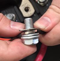
Charge connection terminal stack
- Monolith terminal. in background of photo
- (Optional) Power Tank terminal.
- Charger terminal.
- (For B- Only) Ground reference terminal. photo note: this is incorrectly shown between/below the charger terminal
- Washer.
- Terminal bolt.
- Ensure that the route for the battery leads is the same as before.
- Ensure that the route for the charger leads minimizes bending and does not contact the protective riser brackets around the terminals.
-
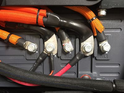
Controller charge connection routing (example)
- Gently but firmly re-tighten the bolts on B+ and B- to 7 Nm ± 1 Nm (6.2ft-lbs) per Sevcon (also recommended 7-12 ft-lbs).
- Confirm electrical connectivity from each terminal to the Anderson connector that terminates the other end of the charger cable leads.
- While still de-energized, re-confirm there is no DC voltage at the terminals.
- Verify low/no resistance from the bolt head at B- to the end of the black cable's lead inside the Anderson connector.
- Verify low/no resistance from the bolt head at B+ to the end of the red cable's lead inside the Anderson connector.
- Prepare the working area for live testing:
- Remove any tools or stray materials from the surface of the controller.
- Route the new charging connection so that it rests away from any conductive elements, including the frame.
- Test live without the charger.
- Key the vehicle on.
- Immediately key the vehicle off on any sign of an electrical fault.
- Verify the contactor closes.
- Verify that there are no reported errors, or only precharge warnings.
- Check DC voltage across the red and black terminals in the Anderson connector housing; it should match expected battery voltage exactly.
- Test charging.
-
| Disclaimer: | TBD Full safety procedure and checklist |
- Fully de-energize the controller again for maintenance close-out.
- Route the new charging connector to its intended destination.
- Ensure that the new cabling cannot be chafed by the edge of the controller cover.
- Ensure that the connector is securely positioned so that it will not strain the controller lug connections or the terminals within the connector housing.
- Ensure that the connector is placed away from splash and dust weathering.
- Re-fasten the controller cover.
- Re-install the seat.
- References

