Difference between revisions of "Gen2/Motor Controller/Connections"
From Unofficial Zero Manual
< Gen2 | Motor Controller
BrianTRice (talk | contribs) (extract from service manual) |
(No difference)
|
Latest revision as of 00:09, 17 January 2020
Main terminals are, in order from front to rear: M1, B-, M2, B+, M3.
|
|
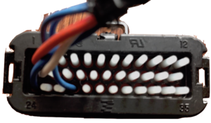
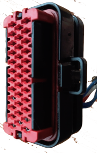
Connector info (see AMPSEAL Automotive Plug Connector and Header Assembly (PDF, English))
|
- Diagnostic Cables
-


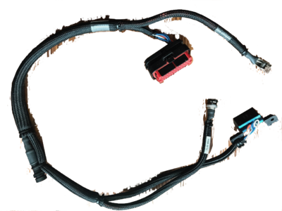
- Zero Sevcon programming cables are part #86-06747 connected as follows:
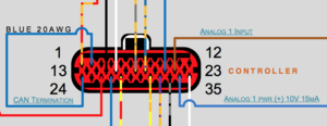
- Pin 1 is "Key Switch In": power for the logic circuits.
- Pin 2 is linked to pin 24 via 120Ω resistor to tell the Sevcon that it's at the CANBus termination.
- Pin 13 is "CAN High".
- Pin 27 is "CAN Low" in the Sevcon manual (pin 24 also is, unless used for termination signal).

