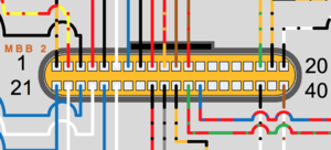
Gen2/Main Bike Board/Connections
From Unofficial Zero Manual
< Gen2 | Main Bike Board
The board has a 34-pin and 40-pin connector exposed through the top of the enclosure, making them relatively accessible and a way to identify the component.
- Both are made by JAE Electronics.
| Connector | Harness-side | MBB-side | Notes |
|---|---|---|---|
| 34-pin connector "MBB 1" | JAE Electronics MX23A34SF1 | JAE Electronics MX34A34NF1. | |
| 40-pin connector "MBB 2" | JAE Electronics MX23A40SF1 | JAE Electronics MX34A40NF1 |
| Component | Function | Wire | MBB Pin | Role |
|---|---|---|---|---|
| Kickstand Switch | Safety Interlock | Red (2013) 20AWG | 27 | Colors are different for 2016 models: |
| Orange (2013) (black) 20AWG | 12 | Blue (5v power), Pinkish Red (measure signal TODO), Black.
| ||
| Yellow (2013) (black) 20AWG | 11 | Kickstand Switch | ||
| Kill Switch | Safety Interlock | Red 20AWG | 23 | |
| White 20AWG | 24 |
| Component | Function | Wire | MBB Pin | Function | Notes |
|---|---|---|---|---|---|
| DC-DC Converter | Enable Signal | Orange (Red) 18AWG |
|


