DigiNow Super Charger Installation (V2)
From Unofficial Zero Manual
(Redirected from DigiNow Super Charger Installation)
This covers a tank install of DigiNow's Super Charger V2.
DigiNow now ships a version 2.5 and prefers a belly pan install; we will cover that separately and soon.
This charger can be ordered in a few different configurations, making it the most flexible charging option currently available.
- This attempts to describe most available options and concerns.
- Your charging arrangement may vary per your requested options.
- Reference
- Supercharger Tank installation with photos
- The following photos feature a MY2016 DSR, charge tank bracket and cowl, and single module SCV2.
- Parts
- (1) J1772 inlet wired for 2 charging units, or 1 charging unit and a split to feed the onboard charger.
- For 3 charging units, two J1772 inlets will be provided, one wired for 2 units and one for 1 unit with an onboard charger split.
- (1 to 3) Elcon HK-J charging units with 12V fans wired and mounted to a simple aluminum heat sink on one side.
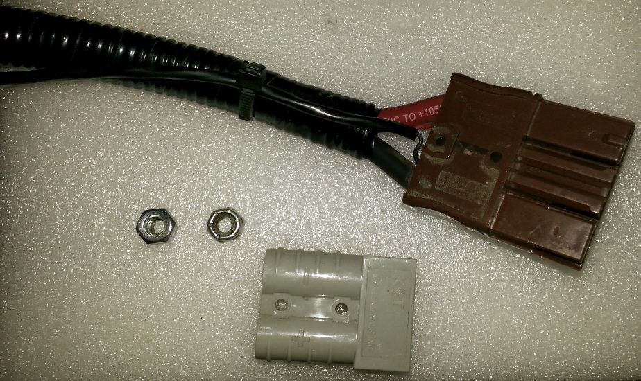
- (1) Y-split cable with two (2) Brown Anderson SBS-75X connectors and one (1) downstream Red Anderson SBS-75X connector.
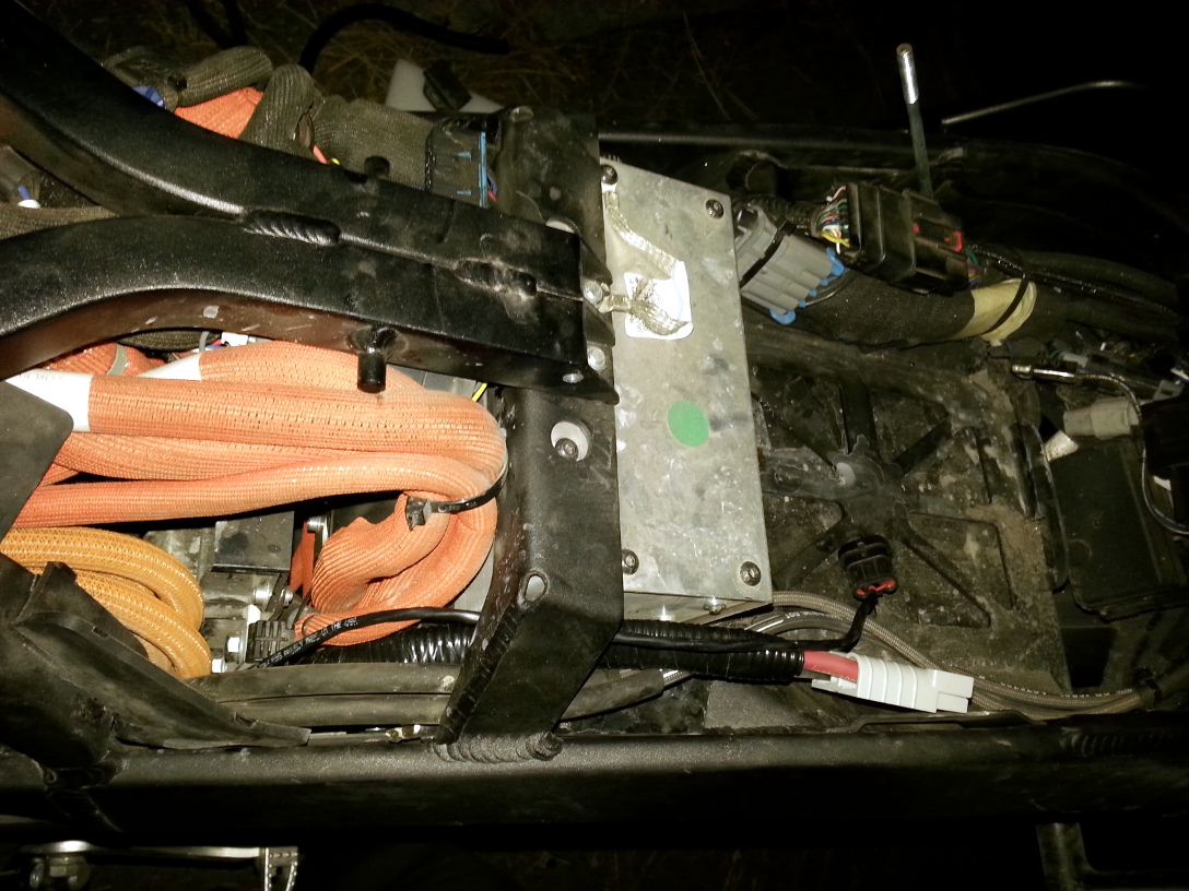
- (1) Potted aluminum box containing the control board. The wiring should connect to each charging unit.
- Instructions
- Discharge your power pack to 75% or lower.
- Power down your motorcycle and unplug the charger, ensuring the contactor clicks open.
- Wait 10 minutes for all components to completely discharge.
- Connect the J1772 inlet to the chargers, and the control board to the chargers.
- Perform an unloaded test:
- Connect the J1772 inlet to a source of 220V power rated for 6.6kW (30A) (via adapter if necessary).
- On early models, verify that the fans turn on and if a light is visible on the control box, that it is lit.
- Station power (if confirmable) should read a few tens of watts, like 40W.
- Disconnect the J1772 inlet.
- Wait a couple of minutes for the charging units to discharge fully before connecting them to the motorcycle.
- Connect the charging system to the vehicle: connect the output Anderson connector to the accessory charging port.
- Turn on the bike and make sure the contactor closes.
- Make sure the bike operates (twist throttle or roll the bike to make sure the controller is engaged).
- Open the Zero mobile app if possible to check charging activity on the battery.
- Repeat the test above with the battery connected and verify charging by the amount of amps reaching the battery in the Zero app Battery Screen.
- Verify that the charge-mode enable signal works by keying the bike off.
- Observe that the bike stays in charge mode and the app continues to report incoming current.
- If this fails, disconnect the inlet from the upstream source and recheck connections once discharged.
- Verify that tapering works at high states of charge by completing a charge beyond 80% SoC. The tapering should happen in concert with battery voltage reading 116V.
- Install Chargetank Inlet Bracket (Optional)
- Prep the aux power wires to be fed through the bike frame.
- (Optional) apply wire routing conduit and electricians vinyl tape also zip tie the signal wire at the one end as a strain relief.
- Going fishing!
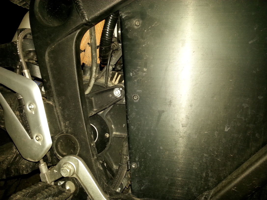
- Stuff something insulated down one side of the frame behind the DC-DC converter.
- The 2016 model year has an advantage to use the right side, while other model years may depend on the right or left side.
- Once you're routed through, you can tightly tape the aux power and control wire ends to your insulated fishing wire and feed back up through the frame.

- Prep the J1772 inlet assembly provided with your Super Charger V2 system
- For use with the Chargetank cowl, you will need to remove the captive dust cap and latch.
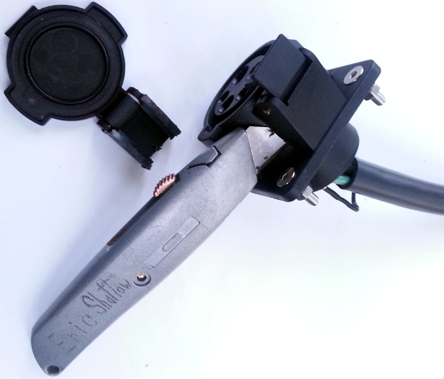
- Also for the Chargetank inlet bracket you will need to elongate the existing fastening holes on the J1772 inlet piece towards the center, so that they will allow for using the Chargetank inlet bracket mounting.
- If you elongate the J1772 inlet fastener mounting holes up to the center most edge of where the countersunk section visibly begins on each hole it will fit very nicely.
- Additionally, there is a circular lip on the bottom of the J1772 inlet that needs to be sanded a few light passes with a rotary tool so that it will seat correctly in the circular cutout in the top of the Chargetank inlet bracket.
- Layout the components of the Super Charger V2 system in place.

- Note the J-hooks which secure the charging module
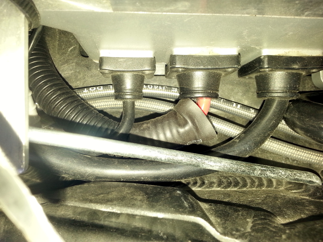
- Take care to insulate or provide strain relief to any cables that might move around or encounter any forces in their lifecycle.
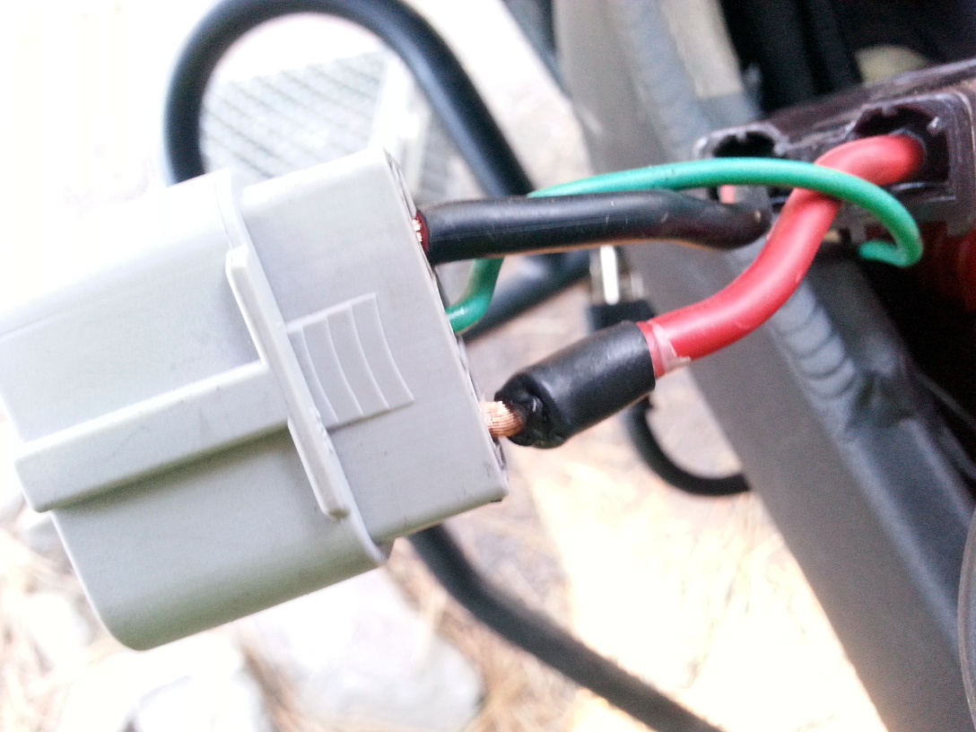
- This J1772 inlet assembly was a very early construction and failed when installed with the Chargetank inlet bracket
- The broken J1772 inlet assembly has been RMA'd and replaced with an assembly that has more forgiving wiring flexibility to work with the Chargetank inlet bracket.
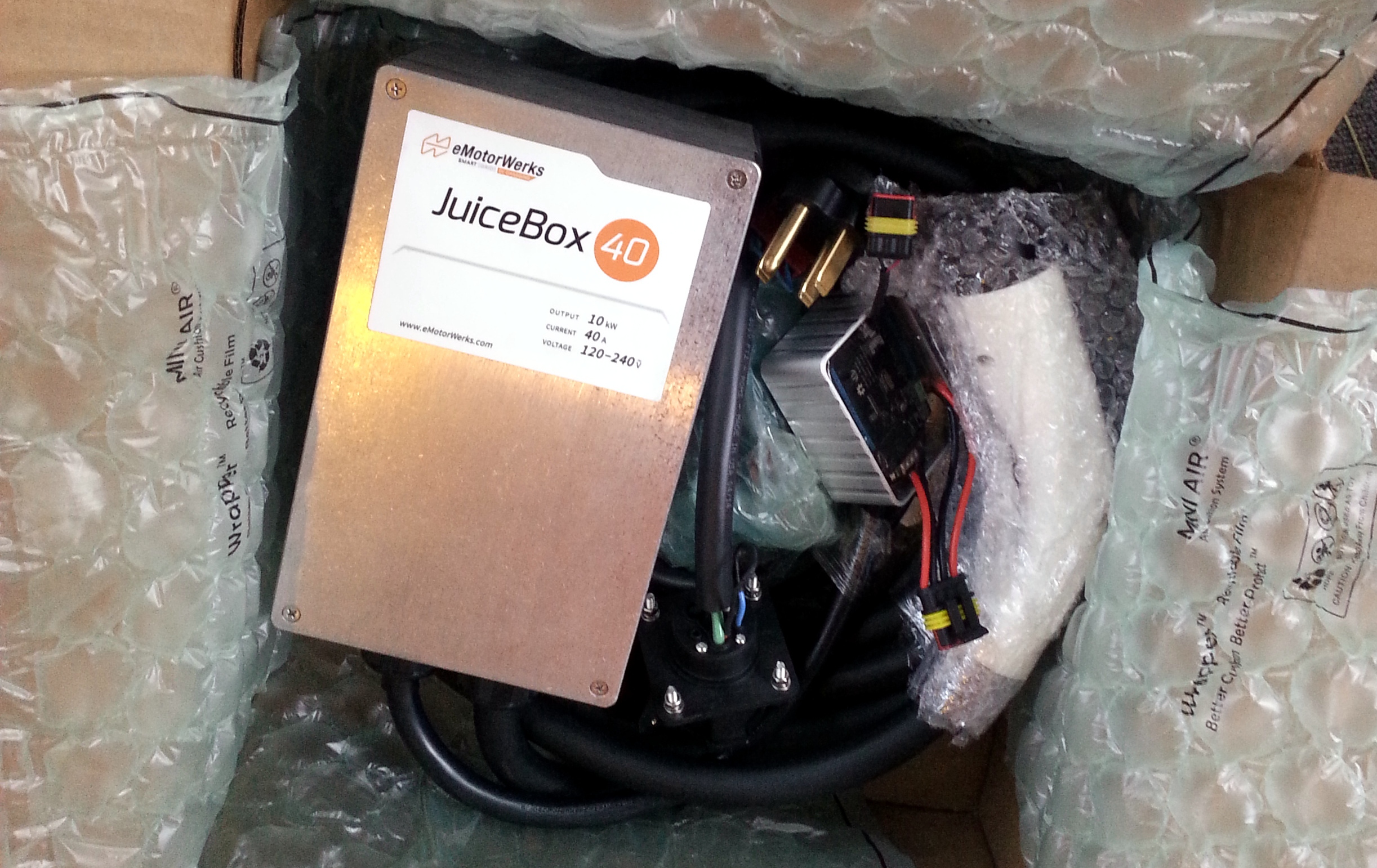
- There was also delivered an EMW JuiceBox 40A charging station (previously available to order with the Super Charger V1), and a new revision of the Super Charger V2 control module that fixes some harmless warning indications induced by the oldest revision.
- The newer revision appears potted in a metal case with a clear epoxy, while the older revision seems potted in a plastic case with some RTV silicone.


- Installing a dual SCv2 under the Chargetank
- Relocate the flasher relay and the clip which holds it to the frame. It can be attached to the Chargetank inlet support bracket.
- The dual modules will fit with the fans forward and the body bolt heads pointing up. If the fan wires don't exit the fans to the top, slowing work the fans out of the airbox to rotate them.