Difference between revisions of "DC-DC 12V Converter"
From Unofficial Zero Manual
BrianTRice (talk | contribs) (multi-platform support) |
(No difference)
|
Latest revision as of 17:49, 22 April 2020
The DC-DC 12V converter is a solid state switching power DC step-down converter designed to produce low voltage DC power from the pack voltage.
| Years | Platform | Manufacturer | Model | Replacement Options |
|---|---|---|---|---|
| 2013-2014 | S and X | Sevcon | Sevcon DC-DC 300W converter | OEM or via Thunderstruck Motors
|
| 2015+ | Sevcon DC-DC 500W converter | OEM or via Thunderstruck Motors
|
- Appearance
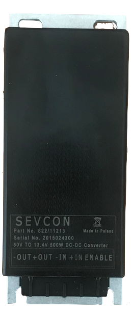
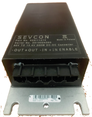
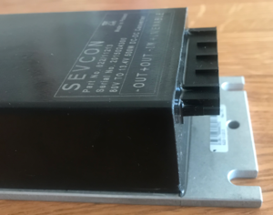
- It's about the size of a long box of soap with a black surface, but for 2013-2014 models will be covered entirely with Nashua aluminum ducting tape, so will appear silver.
- SDS Platform Location
- Below the front of the seat under cable runs, between the MBB (separated by a bracket) and the back of the battery frame area.
- Quick and dirty illustrative video of how to find and access the converter
- XMX Platform Location
- Below the removable battery compartment. See our FX teardown layout guide.
- FST Platform Location
- Inside the tank, on the right of the bin, on the board mounting plate.
- Protections
- Ingress: IP67
- Short circuit overload
- Reverse polarity
- Fully isolated
- Can parallel with diode safeguard
- Mounting
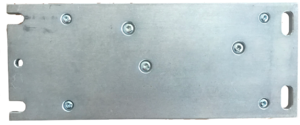
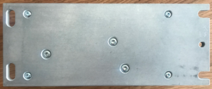
- The Sevcon 500W DC-DC converter is mounted to its own baseplate via 4 Torx T10 cap head screws and there are 3 additional Torx T15 cap head screws in the middle.
- The Sevcon baseplate is then bolted to Zero's board mounting plate with 4 10mm hex head bolts which have 6mm outer diameter, 16mm length, and 1mm pitch.
- Removal
- Remove the board mounting plate.
- Remove the converter from the board using a 10mm hex socket wrench.
- Disconnect the connector if appropriate.
- Installation
- Attach the converter to the board mounting plate with a 10mm hex socket wrench.
- Install the board mounting plate with the converter back into the bike.
- Connections
- There is a 5-pin connector controlling the converter, facing the left as installed on the bike, connected as follows:
| Pin | Function | Measurement | Component | Years | Wire | MBB Pin | Illustration |
|---|---|---|---|---|---|---|---|
| 1 | Enable signal | Battery voltage when key is on | MBB | 2013 | Orange (Red) 18AWG | 21 | 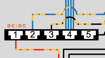
|
| 2015 | 20 | ||||||
| 2 | Input (Positive) | 116V | Battery | 2013 | Orange (Blue) 16AWG | 7 | |
| 3 | Input (Negative) | 2013 | Orange (Black) 20AWG | 5 | |||
| 4 | Output (Positive) | 13.5V | Fuse Block | 2013 | Blue (16AWG, 14AWG) wires | ||
| 5 | Output (Negative/Ground) | 12V return conduits | 2013 | Black 10AWG |
- Output
- It is configured to output 13.5V DC; usually produces ~13.8V DC.
- There is very little ripple that is typical of a gas-power motorcycle's alternator-driven DC supply.
- Capacity is 300W (20-25A) for pre-2015 bikes and 500W (35-40A) for 2015+ models, with most of that excess needed to run ABS pumps, etc.
- Operation
- The input side is always-on DC from the battery, upstream of the contactor.
- This is the best place to tap for an always-on power supply.
- The converter is enabled by a 12V signal from the MBB.
- Environmental Vulnerability
- The Sevcon DC-DC converter is rated to IP67 for intrusion protection and seems very robust as such.
- However, the connector is not sealed, faces the left side of the inside of the frame arms with not much splash protection from beneath; on 2015+ models, it is also vulnerable to debris and splash impact from the rear near the motor and belt.
- No sealed connector option is currently available for Sevcon's DC-DC converter models that Zero uses.
- Connector looseness could age and wear the converter prematurely due to sporadic voltage input or output changes.
- Leakage across pins could cause the enable signal to activate inadvertently.
- Connector Inspection
- Try to inspect the pins' tabs to ensure they are in the right shape to clamp that enable pin securely.
- The connector is not well-sealed, and the pins are too easy to bend into not-connecting if there's any tension/tugging on the wires.
- If the connector seems grimy, remove and clean it while de-energized; then apply grease once dry before re-seating it.
- Test the connector before fully re-assembling the bike.
- Failure to De-energize Condition
- The converter can fail in a way where it shorts its enable line and will not turn off even if the bike is keyed off.
- If this condition happens in rain:
- Let the bike dry out until it clears.
- Attempt a dielectric grease application to the inputs while de-energized.
- If this condition happens in rain:
- If the DC system output disappears:
- Check DC voltage upstream of the fuse block in case the fuse block is faulty.
- Check the continuity and snugness of the connectors and pins.
- Check for the enable signal from the MBB
- Continuity: < 1Ω between pins.
- Not shorted to B+?: > 151kΩ from pin 20 to pin 7.
- Not shorted to ground?: > 1MΩ from pin 20 to 18.
- Protection Recommendations
- Splash protection around the left-side's connector from all sides is worth considering.
