Difference between revisions of "SDS Platform/Electrical Routing"
From Unofficial Zero Manual
BrianTRice (talk | contribs) (new category) |
(No difference)
|
Latest revision as of 22:43, 15 April 2020
This describes routing for the 12V electrical system on SDS Platform models.
- For power cable routing, see the Power Cable Routing article.
- Under The Seat
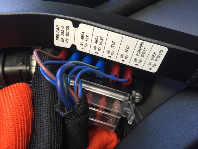
- The 12V fuse block is bolted under the Y-shaped frame bracket under the seat.
- The underside terminals lead to the positive terminals from the DC-DC converter below on its left side.
- (The following picture has one flaw: the fuse label is rotated 180°; layout is reverse of the label)
-

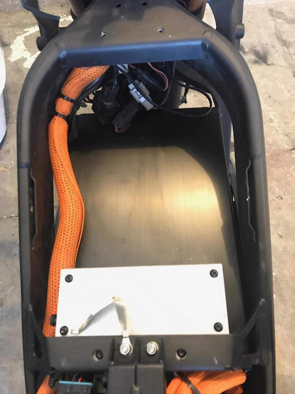
- The terminals on top enter a mesh sleeve, through a ferrite ring to clean up RF interference, and lead forward into a larger sleeve that runs along the left side of the forward tank area.
- The 12V accessory port cable is lower gauge than the others and has a crimped connection that splits into two circuits for 2014+ models.
- The positive side crimped connection is just two inches from the fuse block under the first sleeve, wrapped in vinyl self-adhesive tape.
- Video Guide
- Tank Area Left-Side Routing
- All cabling leading to the steering controls and instrument cluster runs along the left side of the frame tank area wrapped in a bundle.
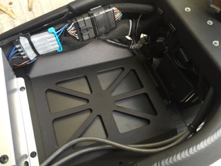
- The largest connector on the left side leads to the instrument cluster. There is a smaller 4-pin connector there for ABS circuits (probably).
-


- Negative/Return
- The negative side connection for all of the forward 12V circuits is halfway along the tank area under a longer stretch of vinyl self-adhesive tape.
- The merged output leads back down to the DC converter between the forward seat and the motor.
- Tank Area Front Mounting
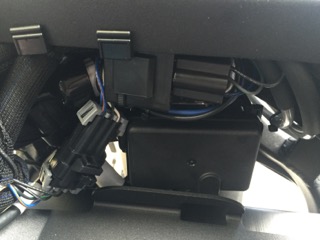
- A group of components are clamped to the underside of the front part of the frame in front of the tank:
-

- The turn signal flasher relay.
- 12V accessory ports: Sumimoto connector and the SAE connector (2014+).
- The 3-pin headlamp connector.
- Tail Routing
- Towards the tail, one sleeved bundle runs past the controller on the left side and handles:
- Turn signals
- Brake and running lights.
- License plate illuminator.
- The turn signal wires run through a pair of holes where the tail stalk meets the subassembly underneath the tail.