Difference between revisions of "Gen2/Instrument Cluster"
From Unofficial Zero Manual
< Gen2
BrianTRice (talk | contribs) (link update) |
(No difference)
|
Latest revision as of 17:41, 22 April 2020
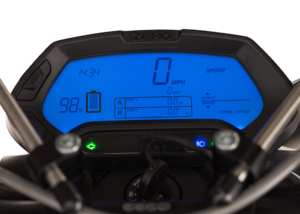
In 2014, Zero introduced their own LCD instrument cluster AKA "dash" for all models (S and X platforms).
- Changes
- The new gauge changed the pin connector and relies on specific CANbus messaging, so there's no simple way to install one on an older model.
- It offers an ergonomic advantage that the instrument cluster no longer obstructs access to the keyed ignition and steering lock.
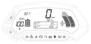
- The state of charge reading is now primarily numeric as a two-digit percentage, with a (effectively) continuous bar level reading next to it.
- Disadvantage: no countable number of increments and also making the rider more aware of state of charge calculation nuances.
- Advantage: It's more accurate, and the dash's other functionality (like range and efficiency readouts) easily compensates for remaining inaccuracies.
- Zero's Official Owners Manual explains its capabilities pretty well.
| Area | Indicator | Source | Adjustment |
|---|---|---|---|
| Left | Clock | Internal
|
SEL+ADJ |
| Time to Charge | MBB | Projected remaining time estimate in hours and minutes. | |
| SoC | MBB | MBB settings
| |
| Bluetooth Indicator | After key-on or the first minutes of charging
| ||
| Center | Speed | MBB settings
| |
| Odometer | Stored in the unit's memory | Unalterable
| |
| A | MBB | To toggle:
| |
| B | To toggle:
| ||
| Right | Drive Mode | mode selector switch on right handlebar | |
| Power | Throttle | ||
| Torque | |||
| Bottom | Left Turn Signal Indicator | Left handlebar turn signal switch | |
| System Warning Indicator | Check System Warning Sequences | ||
| Temperature Warning Indicator | Controller, Motor, or Battery Temperatures at Stage 1 | ||
| Check Engine Indicator (2018+) | Error Codes triggered permanent torque reduction | ||
| Drive Mode Enabled | Green light is:
| ||
| ABS Indicator | Whether anti-lock braking is operational:
| ||
| Charging Indicator | Green LED is:
| ||
| High Beam Indicator | Left handlebar headlamp switch | ||
| Right Turn Signal Indicator | Left handlebar turn signal switch |
- Mounting
- This instrument cluster has two M6 (6mm diameter) threaded rods extending from the rear of the enclosure, captured against the plastic shoulder pieces to the headlamp assembly by two 10mm nylon locknuts.
- Remove the display before removing the plastic shoulder pieces, and re-intall the plastic shoulder pieces before re-installing the instrument cluster.
- Common Problems
- Clock skew
- The internal clock is separate from the MBB clock so can drift over time, often faster by minutes per month or so.
- Loss of indication
- When these have issues, it has mostly been due to moisture entering the (relatively well-sealed) housing.
- This can be disassembled for cleaning but would need re-potting with dielectric grease perhaps when re-assembling and need to be very clean and try inside.
- Loss of Clock
- When the clock reads 00:00 and will not respond to adjustments, it is likely that its internal battery has failed.
- Confirm by observing the indications on startup. If "EEE" appears in the main speedometer readout, the battery is likely dead.
- Moisture Ingress
- The instrument cluster's operation depends entirely on being perfectly sealed.
- Any gaps in its insulation can compromise it eventually.
- Diagnostics
- See MBB Console Dash command
- Assembly
- Enclosure
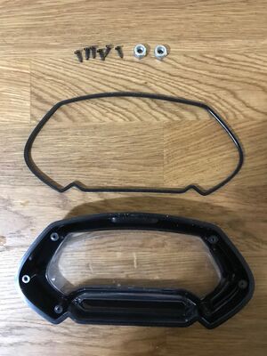
- This instrument cluster is enclosed by a plastic housing, with the back half fastened into the front.
- The enclosure is fastened by 6 black-finished Philips-head (PH1) machine screws at the rear.
- The halves are joined with a rubbery gasket along the edge in a little baffle zone to impede ingress by moisture and dust.
-
 Warning:
 The seal here appears to be critical to the longevity of the instrument cluster's display and circuits. - Internals
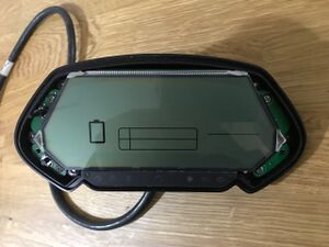
- Within the enclosure, the board is fastened to the rear plastic half by 4 Philips-head (PH1) machine screws.
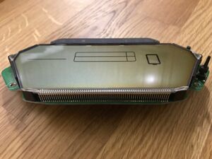
- The board's front consists almost entirely of the LCD substrate with no protection - the protective acrylic screen is part of the front half of the plastic enclosure.
-
 Warning:
 Avoid touching the screen or letting dust fall on it. Clean gently with a lint-free cloth as necessary. - The LCD is connected to the circuitry on the rear of the board by pins along the top edge.
- The Select and Adjust buttons trigger micro-buttons on the left side of the board, which have very small plastic extensions linking them to the rubbery buttons.
-
 Warning:
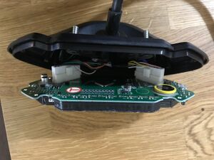
 Take care when uncovering these buttons not to lose the thin button extensions. - The rear of the board displays the circuitry driving the display.
- On the right side of the rear of the board, the internal battery is held.
- The battery is a 3V lithium CR2032 cell, which can be replaced with a carefully-chosen cell.
- Connections
- Two connectors at the rear of the board join the circuitry to the signaling interface with the rest of the bike (via CANBus).
- The connectors are fastened with a simple clip.
- The cable entering the rear of the enclosure is fastened to it by a simple plastic clip and a Philips-head (PH1) machine screw.
- Removing the cable should first involve unclipping the board connectors before loosening the screw holding the cable clip.
- Articles
