SDS Platform/Frame
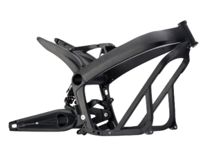
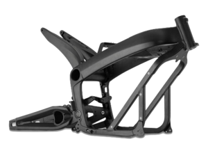

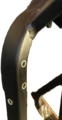
- The 2013+ Zero frame for S/DS/SR/DSR bikes is made of anodized aluminum, weighs 23lbs, and is a combination of cast parts and welded square tubing of 1-inch outer width.
- The frame slips onto the battery pack case over the top and attaches to it with four major bolts around the bottom. The charger is attached to the underside with a protective plate covering it (plastic for S/SR, aluminum for DS/DSR).
- Attachment Points
- The frame offers a number of rivet nut attachment points for the lower plastics.
- The rivet nuts are sized to accept M5 bolts (a total depth of 20mm is available without marring the inside of the frame bar) with a 6mm shoulder to a depth of 5mm. (A longer shoulder and length are required for fastening a bracket beyond that.)
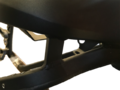
- From 2015 onwards, the frame has extra attachment points made for the crash bars used for fleet/police models.
- Two extra rivet nut holes on each side of the frame diagonal shoulder of the same size. They are 30mm apart (center to center).
- The lower bash plate has similar modifications from that year - two rivet nut holes pre-made for M6 bolts and capped by threaded plastic inserts on each side for the lower mount. There is perhaps 10mm thread depth or allowance between the outer surface of the plate and the onboard charger enclosure.
- On prior year models, the OEM or dealer would make these fittings.
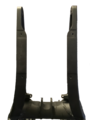
- Vertical Stanchions
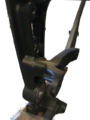
Vertical Stanchion Right
Vertical Stanchion Right
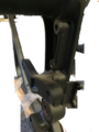
Vertical Stanchion Right
Vertical Stanchion Left
Vertical Stanchion Left
Vertical Stanchion Left
Vertical Stanchion Left
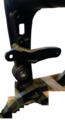
Vertical Stanchion Left
Vertical Stanchion Left


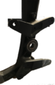
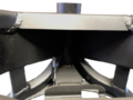
- Tail Horns
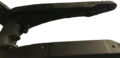
Tail Horns (Left)
Tail Horns (Top)

Tail Horns (Rear)


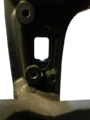
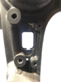
- Neck and Shoulder
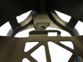
Neck and Shoulder (Top)
Neck and Shoulder (Rear)
Neck and Shoulder
Neck and Shoulder (Left)


- Battery Carrier Tray
Battery Carrier Tray
Battery Carrier Tray (Left Holes)
Battery Carrier Tray (Right Holes)
Battery Carrier Tray (Rear)


- Board Mounting Plate
Board Mounting Bracket (Left)
Board Mounting Bracket (Right)


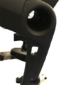
Frame Tube

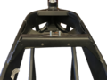
The frame has a tube running through the center of the bike where the tail horns meet the vertical stanchions and the main forward frame beams.
- The tube functions as the anchor and hinge support for the rear shock.
- For 2012-2014 models, this inner tube functions effectively as storage for the Charger Power Cord.
- 2015+ models have a brace in the center of the hole which reduces the diameter in that section.
- The rough edges on this brace can abrade the power cord, so for these models, storing the cord there can wear it out over time.
| Inner diameter (2015+) | ~58mm |
| Center Brace minimum diameter (2015+) | ~40mm |
- References
- Re: Through-frame security aperture size?
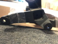
Belly Pan
The Belly Pan AKA Skid Plate covers the onboard charger and is metallic on the DS/DSR and a very hard ABS plastic on the S/SR models.

Both variants are sturdy enough to support the bike on a centerlift.
- Parts
- S/SR: Hard plastic, part 24-07746.
- DS/DSR: Aluminum alloy 5052-H32, part 26-08051 (was 20-05126).
- Dimensions
- Lengths
- 20.5in from forward bevel lip to trailing edge below the motor.
- 14.5in along the flat base.
- 2.25in along forward bevel.
- Widths
- 10.25in at the vertical outside face.
- 11 15/16in edge to edge of the flange facing the frame.
- Heights
- 2.5in from frame-facing edge to the bottom edge (not counting louver overhang).
- 1in height 45° bevel.
- Thickness
- 3mm for the DS/DSR metallic pan.
- Drop bar Mounts
- 2× holes per side for M6 bolts, 45mm center-to-center forward to aft.
- Mounting
- Fastened by 8 M5×16-8.8 button head bolts, 4 per side.
- Forward corner bolts fasten into corner brackets (part 20-05307) that extend the lower frame square tubing.
- Video Guide
- How to Remove the Zero's Onboard Charger by NewZeroLand on YouTube from the beginning to 2 minutes in shows very clearly how to remove the pan from a Zero SR.
- Tools
- 3mm Allen key.
- Steps
- (Optional) Place the bike upright on a front wheel stand if a vertical drop of the pan is suitable.
- Loosen each of the 8 bolts retaining the belly pan (4 per side), without removing.
- Remove each fastener in some suitable rotation so the pan isn't temporarily left dangling by one fastener.
- The pan is lightweight and can be manually suspended if convenient, or use a lift to catch the pan and lower it.
- Set the bolts aside with the pan for replacement later.
Y-Shaped Underseat Frame

This frame piece spans the top of the frame between the part that sits behind the battery doghouse and the tail.
- Functions
- Support and anchor the seat by two pins extending from the forward center section.
- Anchor the rear of the tank plastics.
- Mount the 12V Fuse Block on the left rear leg.
- Distributes the seat loading between the forward frame bracket arching over the monolith, and the horns of the rear tail.
- This protects underlying cabling, as well as dampens any load on the frame that would flex the tail relative to the forward part of the frame.
- Removable (vs being frame-integrated or welded) for servicing everything above the motor (MBB, DC-DC converter, and cabling and wiring).
- Mounting
- Forward: 2x 10mm hex nylon locknuts, with washers.
- Rear: 2x M5 socket cap bolts, 20mm length with a 2mm shoulder, 1mm depth, 6mm outer diameter, with washers.
- Tools
- 10mm hex socket wrench with at least 20mm of depth.
- 5mm Allen key.
- Steps
- Remove the seat.
- Use the 10mm socket wrench to loosen the locknuts anchoring the forward end of the washers.
- Use the 5mm Allen key to loosen the bolts at each of the rear ends of the frame piece.
- Remove the locknuts and the bolts in a coordinated pattern to avoid putting it under asymmetrical loading.
- Take care not to lose the washers in the frame piece or in the bike's cabling areas underneath as each bolt and nut comes off.
- Installation
- Ensure the underlying cabling is placed in its original orientation to avoid strain.
- Press the frame piece's fastener holes onto the corresponding threaded bolts on the frame arch over the rear of the battery.
- Align the rear ends of the frame piece with the corresponding frame holes, and thread the bolts with washers gently into position (without tightening) to secure the frame piece.
- Thread (without tightening) the front locknuts with washers onto the forward bolts.
- Tighten the two forward nuts and rear bolts in a coordinated pattern to settle the frame piece into the right load-bearing orientation.
- Take care while tightening not to strain any cables or wiring underneath the frame piece.
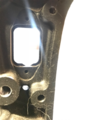
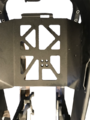
Board Mounting Plate


A vertical plate aft of the battery supports both the Main Bike Board and the DC-DC 12V Converter.
The plate varies between pre-2015 model years and the following model years, likely because of the DC converter upgrade in 2015 from 300W to 500W to support ABS braking equipment power requirements.
- Attachments
- The Main Bike Board is mounted to the rear face of the plate for 2013-2014 models, and to the rear face of the upper edge of the plate on 2015+ models.
- The DC-DC 12V Converter is mounted to the forward face of the plate for 2013-2014 models, and to the lower rear face of the plate on 2015+ models.
- The Accessory Charging Port is screwed to a flange at the bottom of the plate via two small M2.5 allen key bolts.
- The rubber boot covering the Accessory Charging Port is attached to the flange via plastic push-rivet.
- One cable run is zip-tied to a slot in the lower left corner of the plate, accessible under the frame arms forward of the onboard charging plug.
- Another cable run is zip-tied a slot in the lower edge of the plate closer to the right side, accessible under the frame arms behind the battery.
- Mounting
- The bracket has side flanges that affix the plate to the left and right sides of the frame.
- The top two corners of the flanges bend to the rear of the bike at a 45 degree angle, which mate to similarly-positioned flanges on the frame sides. The frame side flanges are above the plate flanges, which means when installing and removing the plate, the top must be angled towards the rear of the bike.
- The bottom two corners of the flanges bend to the rear of the bike at a 90 degree angle. The bolts which affix these corners point upwards (cap head points down).
- Fasteners
- 4x M4 socket cap bolts, 12mm length, 0.75mm? depth, 5mm outer diameter, with washers.
- 2x M2.5 socket cap bolts, 25mm length with a 6mm shoulder, 0.5mm? depth, 2.5mm outer diameter, with washers.
- 2x M3 socket cap bolts, 10mm length, 0.75mm? depth, 4mm outer diameter, with washers.
- Tools
- 2.5mm, 3mm, 4mm Allen keys.
- Low clearance (under 20mm) 3mm Allen key.
- Steps
- Remove the seat.
- Remove the underseat Y-shaped frame piece.
- Detach the MBB by removing the two bolts holding it to the plate with a low-clearance 3mm Allen key.
- The right side bolt will be extremely difficult to manipulate given the cables routed very close to it; consider displacing them.
- Push the MBB aside to the left without unplugging its connectors.
- Remove the two bolts attaching the upper left and right corners, facing 45 degrees up/forward, with a 2.5mm(?) Allen key.
- Remove the two bolts attaching the lower left and right corners.
- Reach them from below the frame arms on each side of the bike, just forward of the stanchions.
- Use a 2.5mm(?) Allen key (preferably a ratcheting socket).
- Snip the cable run zip tie on the lower left corner of the plate.
- Snip the cable run zip tie on the lower edge of the plate from the right side.
- A long, narrow-bladed screwdriver can be suitable.
- Detach the Accessory Charging Port from the lower flange of the plate using a 2.5mm(?) Allen key on the two narrow bolts through the plug's body holes.
- Along the lower rear-facing edge bracket flange, push the cross-frame cable run off of the bracket.
-
- Pull the top edge of the plate to the rear of the bike so that the top mounting flange's corners clear the mating flanges on the frame.
- Gently pull the plate by the DC-DC converter up and aft, minding any cabling that can get snagged on the plate to avoid straining any wires.
- It seems easiest to pull the left side of the plate up first, to avoid clearance issues around the hydraulic lines running along the right side towards the rear brake system.


- Installation
- (Still working on this; essentially reversing the removal but considering the various fitment dependencies ahead of time to avoid trouble).